Transmitting Omnidirectional Antenna
Antenna Introduction:
The antenna is the air interface connection between the Python Detector and the transmitted signal from a emergency services vehicle.
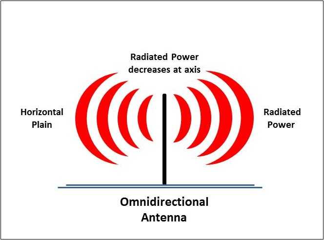
Antennas come in may forms and sizes but the most common types of antenna used in mobile communications are Monopole or Dipole antennas and are Omnidirectional antennas. The radio waves from a transmitting Omnidirectional antenna radiate power uniformly in all directions on the horizontal plane.
The transmitting antenna radiates maximum power in the horizontal plane and this decrease with elevation above or below this horizontal plane and falls to zero at the antenna's axis and viewed from the side the radio waves from a transmitting Omnidirectional antenna form a doughnut shape.
Omnidirectional antennas are oriented (polarized) vertically. Dipole antennas are ground independent, meaning they are designed to perform efficiently with a minimum or no ground plane.
Antenna Length:
The length of the antenna is one important factor on its overall performances, the length is determined by the radio frequency that you want to transmit or receive on, and its wavelength. The antenna length can be calculated by this simple formula: λ = c / f
Where:
λ = wavelength
c = speed of light (299,792,458 Meters Second)
f = frequency (382500000 MHz) for a Tetra Received Signal
We can calculate the wavelength and full antenna length:
299,792,458 ÷ 382500000 = 0.7833 Meters (783.3mm)
To make this full antenna length more practical for day to day applications the length can be reduced in whole number multiples, these are often referred to as 1/2, 1/3, 1/4 and 1/8 wave antennas.
For example a 1/4 wave Tetra antenna would be:
783.3 / 4 = 195.8mm
Antenna Gain:
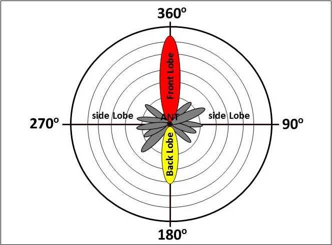
Antenna gain is the relative measure of an antenna's ability to direct or concentrate radio frequency energy in a particular direction or radiation pattern. In a receiving antenna such as used in Python, the gain is how well the antenna converts radio waves arriving from a specified direction into electrical power. When no direction is specified, "gain" is can be referred to the peak value of the gain, the gain in the direction of the antenna's main lobe.
Transmitting Antenna Pattern
Low Gain omnidirectional antennas:
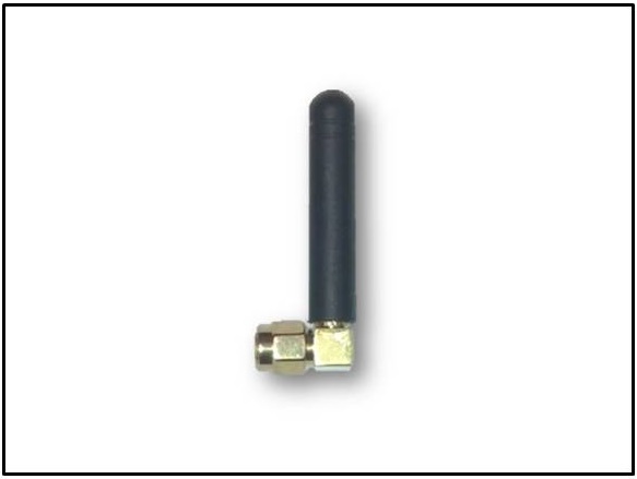
As used in our Standard Antenna are a helical construction where the antenna wire is formed into a helix allowing the antenna to be smaller.
Low Gain antennas radiate at a wider angle and in general have a shorter detection range but can give good level of detection in an urban or hilly environment.
Higher Gain omnidirectional antennas:
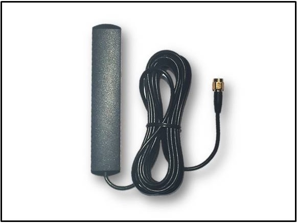
Such as our Windscreen Antenna or an aftermarket Magnetic Roof Mounted Antenna radiate at a lower angle in a more horizontal direction providing greater detection capability in an open environment such as a motorway where there is a relatively flat and open topology.
Antennas Radiation Patterns:
Dipole antennas are oriented vertically and are typically used for non-directional applications where the received signal can be detected from all directions (360 degrees). The types and positions of the antenna and their radiation pattern can determine the detection capability.
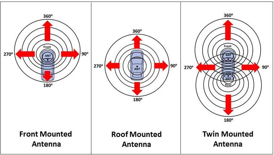
Radiation Pattern for Different Antenna Mounting Positions
Front Mounted Antennas:
Our Standard Stubby or Windscreen Antennas give good all round detection with a slight radiation bias pattern to the front of the vehicle.
Roof Mounted Antennas:
Roof mounted antennas give a slightly better all round detection with an equal radiation pattern.
Twin Mounted Antennas:
You can also use a combination of front and rear antennas and in this type of installation you would need to use a combination of Low Noise Amplifier and Splitter.
The Detection Range:
The detection range depends on a number of factors such as:
1. The strength of the transmitted signal received by the detector.
2. The distance from the transmitted signal from the detector.
3. The timing on when the Emergency Services Radio first transmitted the tetra RF signal and the distance to the Python Detector.4. The distance from the transmitted signal from the detector.
5. The surrounding terrain and topology.
In an open environment such as a motorway where there is a relatively flat and open topology the detection distance may be greater, and in an urban environment where tall buildings or other topology may block the signal to the detector and the detection range is decreased. The following table give an approximated detection range for our different Python Detection and Antenna option:
Note: The detection distance are based on calculated figures
Considerations during Antenna Installations:
In general antennas should be mounted as high as possible, there are some consideration to the position of the antenna is needed to avoid blocking the RF signals to your detectors.
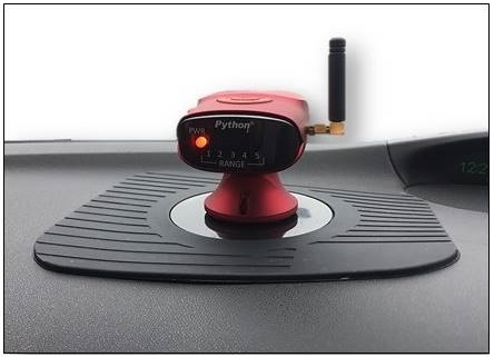
Dashboard Installation with a Stubby Antenna
Antenna Position:
If you are using the Standard Stubby Antenna supplied with your detector ensure that the detector is mounted on your dashboard or windscreen. If you mount the detector below the height of the dashboard you will reduce the detection capability. If you want to mount the detector in your centre console then we suggest to use a Higher Gain Antenna, these can be either windscreen mounted or Magnetic Mounted.
Infrared Reflecting Windshield
Newer types of vehicle windscreens can contain a metal oxide that help to keep the interior from getting hot but they also block the Transmitted RF Signals to the Antenna.
Antenna Mounting Considerations with an Infrared (UV) Reflecting Windscreen:
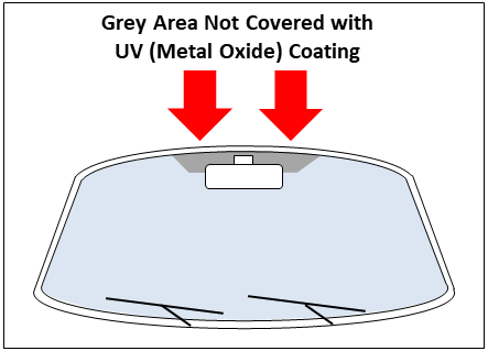
Grey Areas indicates suggested mounting
locations for RF type devices
Infrared (UV) Reflecting Windscreen:
Newer types of vehicle windscreens can contain a metal oxide that help to keep the interior from getting hot but they also block the Transmitted RF Signals to the Antenna.
Most vehicle manufactures provided details in their user manual on the suggested mounting locations for RF type devices, a typical example is shown in the picture opposite where the grey areas are not covered in a UV (Metal Oxide) coating and RF type devices (including our Python Higher Gain Windscreen Antenna should be located.
Caution: Make sure you do not position the detector in your normal clear field of vision. This will block your safe view of vehicles, motorcycles, cyclist, pedestrians and other potential hazards.
Preferred Mounting for your Python Windscreen Antenna on a (UV) Reflecting Windscreen:
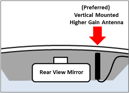
Preferably for the best detection our Python Higher Gain Windscreen Antenna should be mounted Vertically as shown in the example picture opposite.
Please refer to your vehicles user manual on the suggested mounting locations for RF type devices and the areas on the windscreen that are NOT covered in a UV (Metal Oxide) coating.
If the Python Higher Gain Windscreen Antenna is mounted on the UV (Metal Oxide) coating area then this will impact the antenna matching and make it “deaf” and less capable to pick up any signals from the emergency services radios.
If the Python Higher Gain Windscreen Antennn can not be fitted Vertically, then please refer to the optional mounting for our Python Higher Gain Windscreen Antenna in the section below.
Preferred Vertical Mounted Python Higher Gain Windscreen Antenna in a UV (Metal Oxide) coated area of the windscreen
Optional Mounting for your Python Windscreen Antenna on a (UV) Reflecting Windscreen:
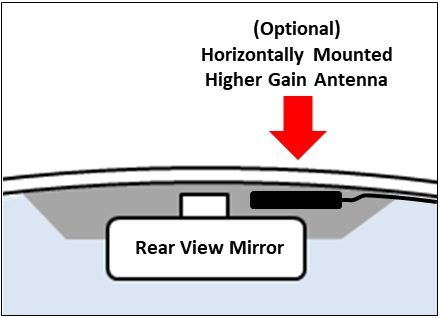
However, if in your particular vehicle it is not possible, and as the RF Tetra signals are mostly reflected, then alternatively you may be able to mount the Antenna horizontally as shown in the picture opposite.
Alternative Antenna Mounting Solutions:
Higher Gain Windscreen Antenna (Side Mounting): Alternatively you may be able to mount the Python Higher Gain Windscreen Antenna Vertically on a Non-opening rear side window. If you need a longer RF cable, please see our accessories below.
Higher Gain Roof Antenna: If the above antenna mount option are not possible, you can always upgrade to Magnetic Mounted High Gain RF Antenna, using a roof mounted antenna will also give you the best detection range, please see our accessories below.
Built-in Radio Antenna or Heated Windscreen or Rear Windows:
Windscreen Installation with a High Gain Antenna
Built-in Radio Antenna or Heated Windscreen:
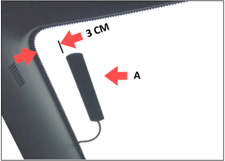
Some vehicle windscreens also have a built-in Radio Antenna and/or Heater Elements; these can block some Transmitted RF Signals to the Detectors Antenna and reduce the detection capability.
If you are using a Higher Gain Windscreen Antenna, we recommend that it must be placed 3 CM from any object that could interfere with the detection.
Please also refer to your vehicles manufactures instructions for the best location for devices that need to receiver a RF signal.
Caution: Make sure you do not position the detector in your normal clear field of vision. This will block your safe view of vehicles, motorcycles, cyclist, pedestrians and other potential hazards.
Heated Rear Windows:
All vehicle now days have a heated rear window, if you are mounting a Higher Gain Antenna in the rear window, ensure that the Antenna is not mounted on top or close to the Heater Elements; as this can block some Transmitted RF Signals to the Detectors Antenna and reduce the detection capability.
Antennas and Accessories:
We have a number of different antenna options available from our store, please click on the below buttons for more information:
You can easily upgrade to our Higher RF Gain windscreen mounted antenna without the need for any special tools
You can increase the detection range of your detector by fitting a Magnetic Mounted High Gain RF Antenna
Our replacement Standard Antenna can be obtained from our store should it be required
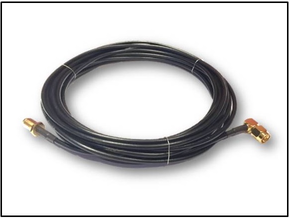
Our 5 metre RF extension cable allows you to mount our Higher RF Gain windscreen antenna in different locations

